MICRON NEWS
Precision Manufacturing Innovations
2023 Mar

Determining if Force and/or Material Testing is Right for your Application
The majority of product testing in manufacturing environments requires the force measurement of samples to verify if they are able to withstand specific load application during post-production. However, throughout the product design and development stages, material properties are also tested and studied to determine if and how the material is an applicable fit for the product. There is a distinction between these two types of tests – force measurement and material testing - and your choice can be simplified by knowing what kind of information you need to collect.
The Difference In Units
First, it is helpful to understand the difference in units. Force testing measures the sample’s ability to withstand or fail under an applied load. These loads are commonly measured in values of pounds-force (lbf) or newtons (N), while height or travel is measured in distance units such as inches (in) and millimeters (mm). Material testing replaces the values of load and travel for stress and strain, which are typically measured in pounds per square inch (PSI, or lbf/in^2) or MegaPascals (MPa, or N/mm^2) for stress, and as a fraction or percentage for strain. The key difference between these two-unit sets is that stress and strain are determined from properties of the material sample itself, rather than just the load being applied.
Consider breaking a cube in half in a uniaxial force tester operating in a perfect system where objects don’t deform under tension. The test is designed to hold the sample by opposing faces, applying a tensile force to break it in half. The resulting halves would be perfect square prisms, each half the height of the original cube. A force test assumes that the size and shape of the cube is irrelevant – either because all of the cube samples are uniform in dimension so that the size and shape would not matter, or the difference in sizes are unimportant as long as the cube reacts properly to the loads being applied. As a result, it would be unnecessary to test in values of stress and strain and instead measure in load and distance.
A material test, however, requires knowing the dimensions of the cube to properly report its findings. Let’s assume the cube is one inch in length on each edge, and it takes 100 pounds of force to break the cube in half. For a force test, the 100 pound-force value is all that’s required for the force system to collect as a data value, but for a material test the system needs to translate that information to PSI. Because it is a perfect cube breaking evenly in half (without stretching), the cross section is one inch by one inch square. To determine the stress at break, the 100 pound-force is divided by the cross-sectional area of 1 square inch, which equals 100 pound-force per square inch, or 100 PSI.
To help put this into context for factoring in variables when material testing, let’s think of a cube with two-inch edges, made of a different material that also breaks at 100 pounds-force. Now that the cube is bigger, so is the cross-section, which is now two inches by two inches, or four square inches. When dividing the 100 pounds-force by that area, the result is 25 PSI. It is a lower stress value – an indication of a generally weaker material. Consider that the area where the break occurs on the second cube is four times the area of the original, but still breaks at 100 pounds of force. If you had a cube of the second material that was one inch on each side like the first one, you can assume that it would break at a lower load value. You can even estimate that value: 25 PSI times 1 in2 is equal to 25 pounds. Operating with that same information, you can determine that the second cube, being two inches on each edge, would have a breaking load of 400 pounds-force; 100 PSI times 4 in2 equals 400 pounds.
The example provided ignores many real-world behaviors for the sake of simplicity, but the general application is the same -- material tests determine the inherent properties of what is being tested, and need to be scaled appropriately for when the samples change size so that they collect information accurately. A force test does not require that information, and can note behaviors under load without needing the material sample test data. Looking at the first test example again, the test goal could be that the sample needs to break before exceeding 100 pounds of force to pass the test. The second material would pass as a one-inch or two-inch cube, but the first would only pass as a one-inch cube, because a two-inch cube would require four times the load to break.
Material Testing Example – Wire Testing
Building on the testing example of a spring, consider that the metal properties of the spring’s uncoiled wire can be assessed through the analysis of stress-strain testing. Unlike when in its coiled form, the lengthwise testing gives an easier means to determine the cross-section upon which the stresses are applied, which is equal to the area of the circle defined by the wire diameter. It also allows for proper measurement of the elongation, as it occurs along the sample’s whole length where appropriately gripped.
Using a wire instead of the coil spring provides an additional advantage. In environments where high precision is required, an elongation measuring tool called an extensometer can be used. These devices are designed to grip the samples at fixed points, and measure the change in distance between two points as the sample stretches. For example, if an extensometer has grips with an initial separation of one inch, and the sample stretches to further separate them by an additional half inch, the recording of the test will note a fifty percent increase of sample length, or elongation. The design of the extensometer often takes into account the intended sample material, and are constructed with physical limits to their maximum travel distance.
Depending on the extensometer, these travel limits might be shorter than the full length of a test stand, but well within the expected limits of elongation based on material ductility. Integrated extensometer units have the advantage of being able to operate with the test system’s software, while independent units can be specifically configured for the material type. For example, longer elongation devices may be used for highly ductile samples, and more durable models are appropriate for less ductile samples so that they can stay on the sample through its break.
2023 Mar
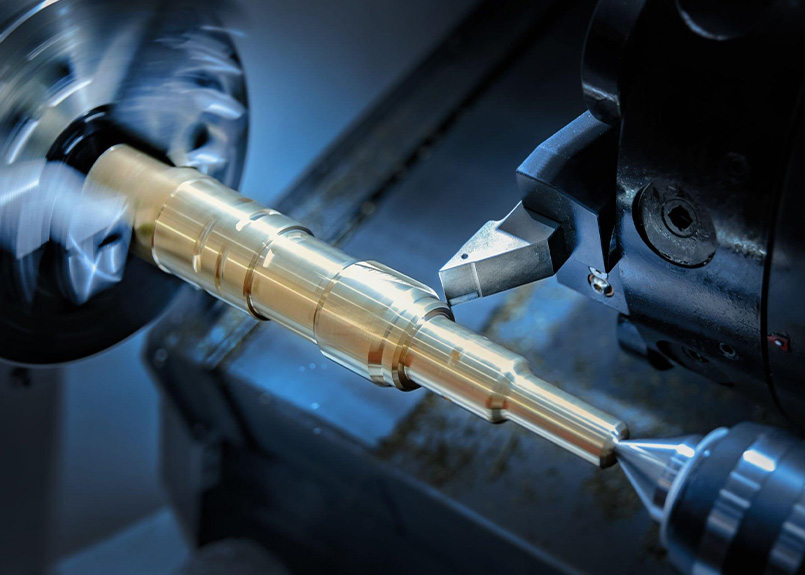
Selecting The Right Solution For Shaft Inspection
Shaft production has historically been, and still is, one of the most common processes in machine tool shops. Shafts are an elementary component of a majority of mechanical systems we use in our everyday lives and as the requirements of higher quality and precision of those shafts have become more restrictive, so have the requirements for inspection of the shaft’s features. Not so long ago, shafts were most often inspected using a variety of hand gages such as profile templates, calipers, micrometers or snap gages. Today, specialized shaft measurement systems better suited for modern shaft production processes are available.
In order to determine which type of gage is best for shaft inspection, various aspects of shaft production and features need to be considered, including:
The machining process being employed
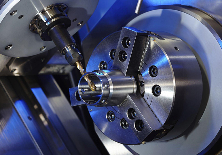
Parts produced by different machining methods, be it turning or grinding, can require different gaging technologies. This is due to the different surface finishes produced, especially if you are considering a tactile measurement solution. Noncontact technologies work very well on finishing operations like grinding and polishing, but may not have the same accuracy or repeatability with rough turning operations, which can display burrs or rough surface finishes.
Production volume
Higher volumes generally call for a more dedicated, perhaps automated, solution that can measure quickly and provide feedback without affecting overall takt times. When it comes to lower volumes, a handheld solution or today’s flexible gaging systems can be practically and economically viable in many cases.
Part features to be inspected
Differing part features may require different technologies or techniques to ensure accurate and repeatable inspection results. For example, certain solutions may not be appropriate for measuring internal features such as keyways and holes.
Range of parts to be produced
The number of various parts being produced and the degree to which they differ will impact the design or type of inspection system that fits best in your process. These factors will influence how much flexibility is required within the measurement solution.
Frequency of part changeover
If you are changing production from one part to another several times a day, a flexible inspection system becomes much more valuable by eliminating downtime otherwise needed for mechanical retooling.
Ergonomic considerations
A gage is only useful if it is usable. The loading and unloading of the part, the sequence of measurement operations, and the operator interface must be practical and understandable. The inspection system must also deliver results that are not influenced by operator skill or bias.
A Variety Of Inspection Technologies
In the past, manufacturers were often forced to choose a dedicated system instead of a flexible one because flexible systems sacrificed accuracy or speed. Today, there are flexible gaging systems that can incorporate several contact and noncontact technologies in one system, giving you the ability to inspect a wide spectrum of features on a multitude of parts while sacrificing very little or nothing in system performance.
Some of the first flexible shaft measuring systems employed a tactile probe on a moving slide. In practical terms, it was a 2D CMM. The advent of scanning probes, which allow the system to collect hundreds or even thousands of data points per scan, helped to increase the accuracy as compared to discrete-point probe systems. Then 2D scanning probes further increased the flexibility of the system to include complex measurements such as gear tooth or spline geometries.
While highly accurate and flexible, the measurement cycles of tactile probe systems are often too slow to keep up with the production rates required, relegating the systems to the measurement lab or periodic audit inspections. In-process gages are still typically custom designed systems that required mechanical changeover between part runs.
Then came the optical gages employing CCD (charge coupled device), also known as matrix array, cameras or line scanning cameras. These devices project light across the part and analyze the silhouette that is created to measure the different part features. This method, often referred to as shadow casting, greatly reduces cycle times while adding even more flexibility for inspecting different shaft configurations. Optical measurement is not susceptible to the variances caused by tooling marks that can affect tactile measurement methods, so measuring parts with differing surface finishes is not as challenging as it once was. These systems also make it possible to inspect shaft configurations that are not strictly rotationally symmetrical. However, optical systems employing this method are limited to inspecting only features that create the silhouette. Features such as keyways and holes, not visible in silhouette, were not able to be measured.
Today, there are systems available that can use any of the above technologies along with others, such as lasers, for measuring the more complex features or high-speed following devices for rapidly inspecting eccentric diameters. These systems are capable of rapidly inspecting not only diameters and lengths, but many complex features such as chamfers, radii, threads, keyway slots, splines and others.
A big development is that advanced filtering routines in optical inspection equipment now allow these systems to be used in shop floor environments versus only within a lab setting, bringing improved measurement and efficiency to the process.
The Importance Of Software
Flexible and user-friendly programming allows you to customize your inspection routines for full production with automated loading and unloading as well as feedback directly to your machine tool for tool wear compensation while giving you the ability to also make periodic audit checks on certain critical features.
The measurement cycles of such systems when used in a manually loaded manner are usually semiautomatic, requiring only the loading of the part and selection of the desired inspection plan. Upon pushing the start button, the inspection is automatically performed and the measurement results can be displayed in a number of ways depending on the needs of the inspector. Graphic displays allow the user to zero in on part features of particular interest.
Shaft measurement can be accomplished in many different ways, according to the needs of the manufacturing process. Handheld devices such as micrometers are still used in many low volume processes, while highly sophisticated lab equipment is used in many metrology labs for periodic inspection and analysis. Tactile probe systems provide flexibility and accurate results, but often sacrifice speed for those features. Optical systems can be much faster but are somewhat limited in the scope of features they can inspect. Combination systems employ a variety of technologies in a single system to offer a high level of speed, accuracy and flexibility for your process.
For fast, accurate and flexible inspection on the shop floor, there are options available to meet the needs of any shaft production line. By considering the factors that define your process – and working with your quality solutions provider - you can make the right choice of system for your requirements.
CONTACT US TODAY
Get In Touch With Us